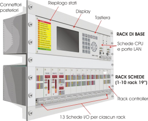
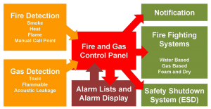
Fire and Gas System Control Panel or Logic Solver is the central control unit of the overall F&G detection and control system. The controller receives alarm and status or analog signals from field monitoring devices required for Fire and Gas detection and handles the required actions to initiate alarms and mitigate the hazardous situation and takes action depending upon the level of hazard detected (process shutdown, fire extinguish release).
 |
The Controller automatically initiates executive actions minimizing escalation of safety incidents and protecting personnel, property and the environment. Integration at the controller level provides plant-wide Safety Instrumented System (SIS) point data, diagnostics and system information, as well as alarms and events, operator displays and sequence of event information to any station. This minimizes intervention and shutdowns, reduces hardware costs, and allows plants to recover more easily from process upsets. |
Safety Integrity Level (SIL) |
||||||||||||||||||||||||||||||||||||||||
| Safety integrity level (SIL) is defined as a relative level of risk-reduction provided by a safety function, or to specify a target level of risk reduction. In simple terms, SIL is a measurement of performance required for a Safety Instrumented Function (SIF).
The requirements for a given SIL are not consistent among all of the functional safety standards. In the functional safety standards based on the IEC 61508 standard, four SILs are defined, with SIL 4 the most dependable and SIL 1 the least. The applicable SIL is determined based on a number of quantitative factors in combination with qualitative factors such as development process and safety life cycle management. The International Electrotechnical Commission’s (IEC) standard IEC 61508 defines SIL using requirements grouped into two broad categories: hardware safety integrity and systematic safety integrity. A device or system must meet the requirements for both categories to achieve a given SIL. The SIL requirements for hardware safety integrity are based on a probabilistic analysis of the device. In order to achieve a given SIL, the device must meet targets for the maximum probability of dangerous failure and a minimum safe failure fraction. The concept of ‘dangerous failure’ must be rigorously defined for the system in question, normally in the form of requirement constraints whose integrity is verified throughout system development. The actual targets required vary depending on the likelihood of a demand, the complexity of the device(s), and types of redundancy used. PFD (probability of dangerous failure on demand) and RRF (risk reduction factor) of low demand operation for different SILs as defined in IEC EN 61508 are as follows:
For continuous operation, these change to the following. (Probability of dangerous failure per hour)
Hazards of a control system must be identified then analyzed through risk analysis. Mitigation of these risks continues until their overall contribution to the hazard are considered acceptable. The tolerable level of these risks is specified as a safety requirement in the form of a target ‘probability of a dangerous failure’ in a given period of time, stated as a discrete SIL. Certification schemes are used to establish whether a device meets a particular SIL. The requirements of these schemes can be met either by establishing a rigorous development process, or by establishing that the device has sufficient operating history to argue that it has been proven in use. Electric and electronic devices can be certified for use in functional safety applications according to IEC 61508, providing application developers show the evidence required to demonstrate that the application including the device is also compliant. IEC 61511 is an application-specific adaptation of IEC 61508 for the Process Industry sector. This standard is used in the petrochemical and hazardous chemical industries, among others. |
Special Applications:
Human Machine Interface: |
|
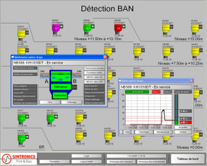 |
The Fire & Gas System shall have a communications integration with other safety systems such as Distributed Control System (DCS) and Emergency Shutdown System (ESD) in order to have Fire & Gas graphics and alarms for display to the operator, meanwhile, there shall be independent displays such as independent Human Machine Interfaces (HMI) to draw attention to fire & gas excursions when the DCS HMIs are not available; The plant Fire & Gas system, with fire system for occupied buildings, shall be integrated with Plant Evacuation and System/Site Security Centre for plant evacuation. As part of an overall plant safety strategy, end users need a unified platform for emergency shutdown and fire & gas detection to have a single window for operators and common tool for engineering and maintenance to drive down operational risk and costs. |
Applicable Notes:
- Fire and gas system engineering is a specialized field made more complex as the practices for designing and maintaining systems through their lifecycle have evolved over the years. Much changed with the advent of prescriptive standards developed by the National Fire Protection Association, European Community and most recently, International Electrotechnical Commission (IEC) 61511 and International Society of Automation (ANSI/ISA) 84.00.01. These standards established performance-based criteria for evaluating the performance of Safety Instrumented Systems (SIS). Technical report TR84.00.07, which was developed under an ISA 84 working group, provides guidance on how fire and gas systems can be designed according to IEC 61511.
Our Services:
SISICO is able to offer an extensive range of Fire and Gas System Control Panel to suit your specific environment from below mentioned companies:

